Tag Archive for MC2300

MC2100, MC2105, MC2300 Can Capacitor Replacement Kit

066-095-PAE

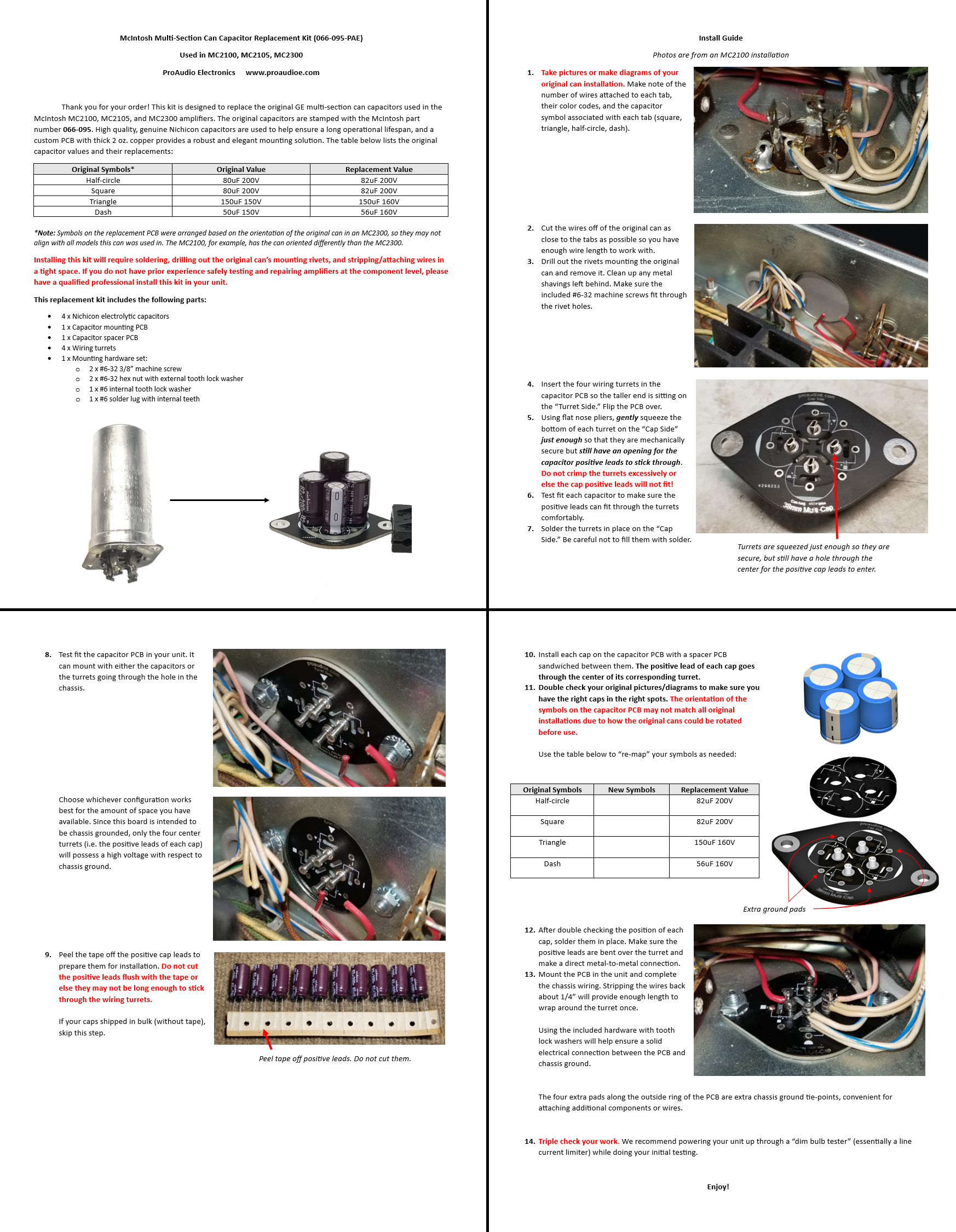
Click the link below to download the installation guide

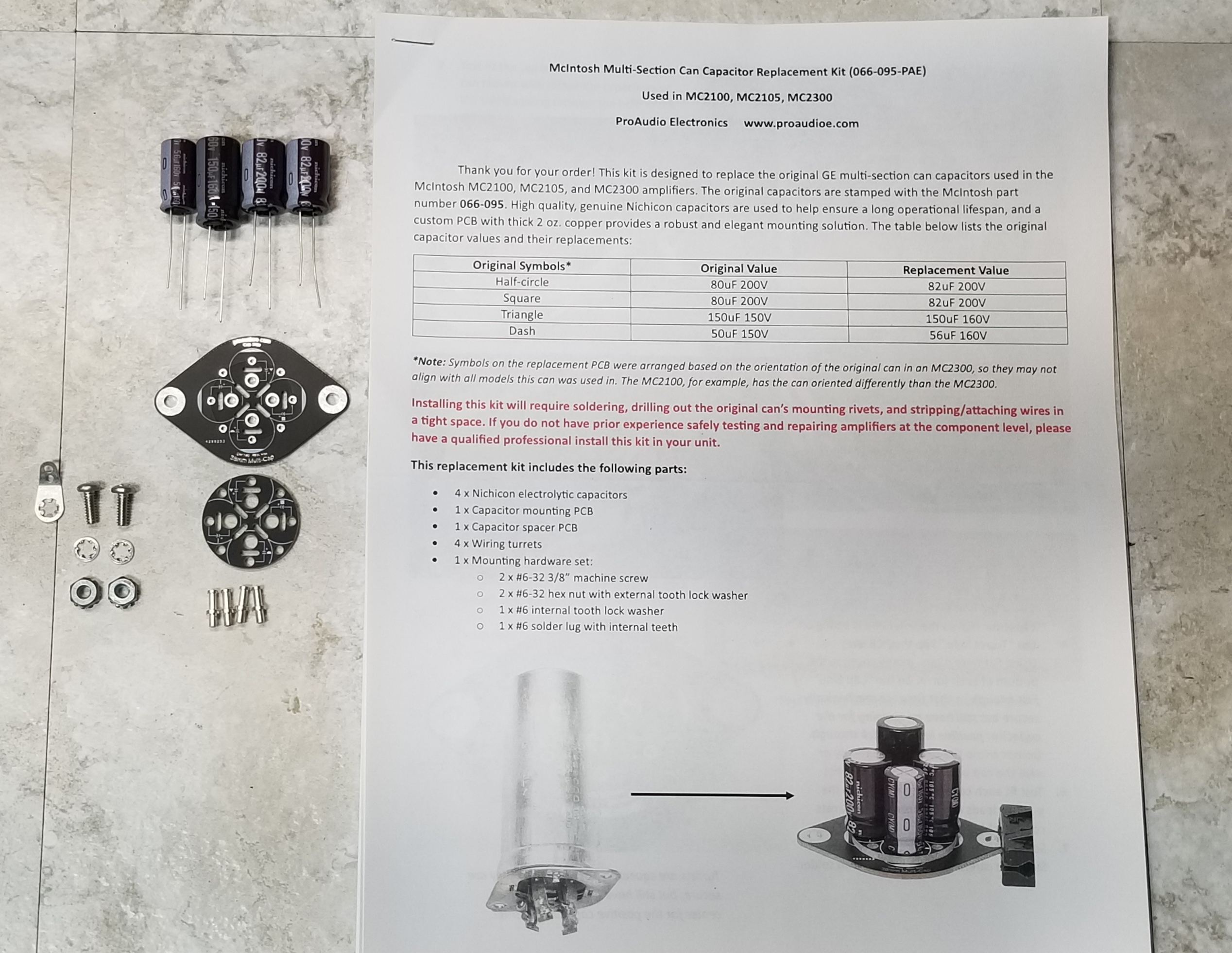
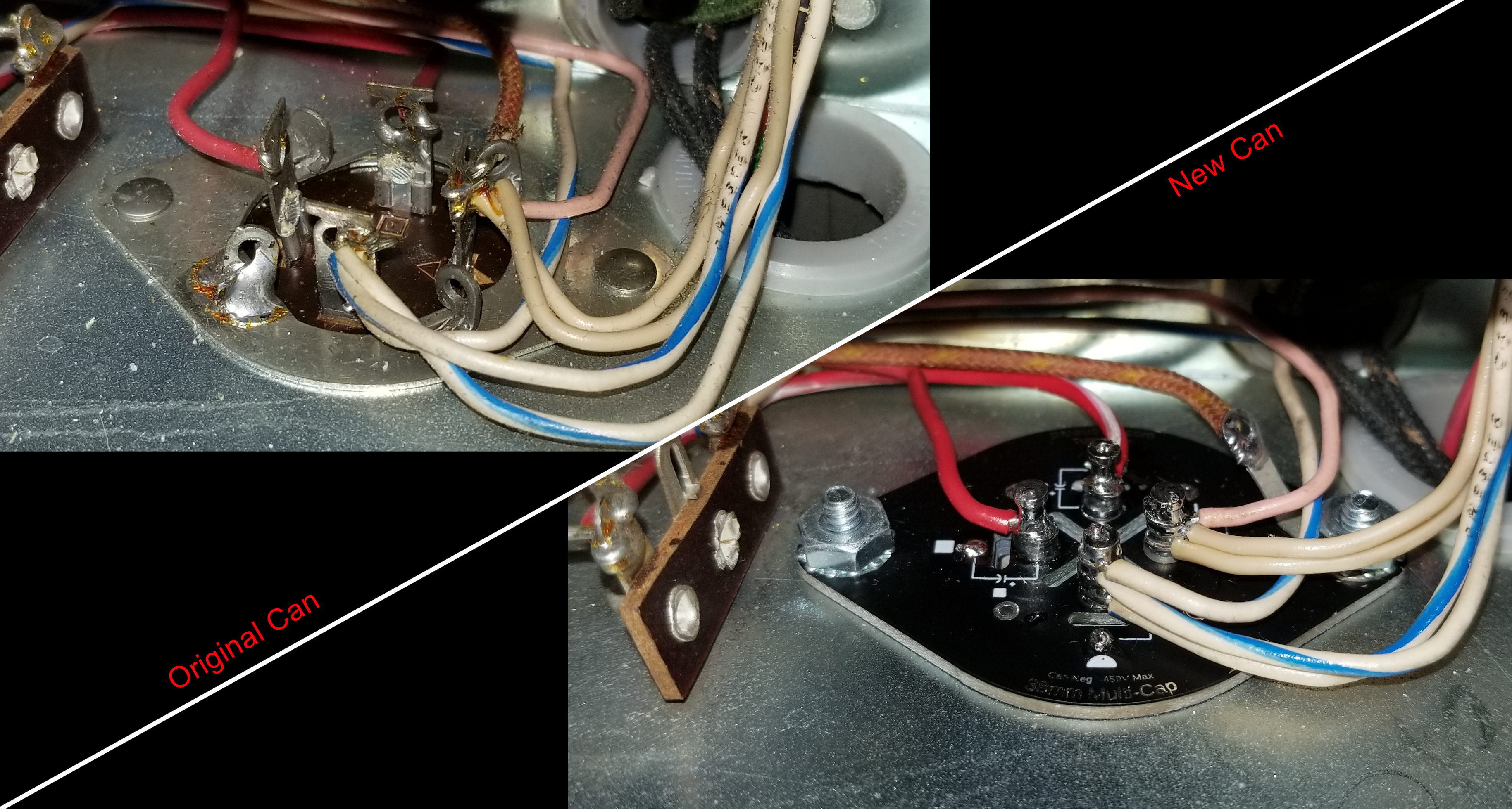
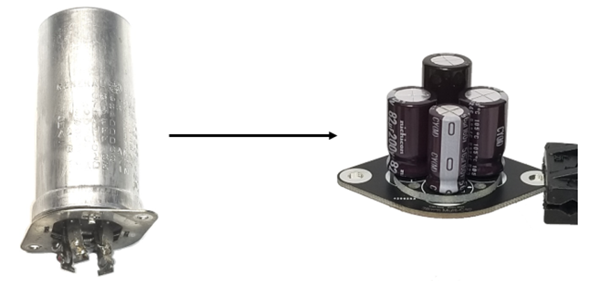
This is a replacement kit for the GE multi-section can capacitors used inside the McIntosh MC2100, MC2105, and MC2300 power amplifiers. These cans were stamped with McIntosh part number 066-095. Other models may also use this can. High quality, genuine Nichicon capacitors rated for operation up to 105°C are used to ensure a long operational lifespan, and a custom PCB with thick 2 oz. copper provides a robust and elegant mounting solution. Four wiring turrets facilitate the connections to each of the four caps. No more gutting the old cans and sticking new caps inside!

Includes four Nichicon capacitors, one cap mounting PCB, one spacer PCB, a hardware kit, and a thorough step-by-step installation guide.

Installing this kit will require soldering, drilling out the original can’s mounting rivets, and stripping/attaching wires in a tight space. If you do not have prior experience safely testing and repairing amplifiers at the component level, please have a qualified professional install this kit in your unit.

The following capacitor values are included:

  • 82uF 200V (Replaces 80uF 200V)
  • 82uF 200V (Replaces 80uF 200V)
  • 150uF 160V (Replaces 150uF 150V)
  • 56uF 160V (Replaces 50uF 150V)

Note: The capacitor symbols (square, triangle, half-circle, dash) on the cap PCB were arranged based on the orientation of the original can in the MC2300. Other models, such as the MC2100, typically had the cans oriented differently, meaning the position of the symbols on this board may not align with your original installation.

MC2100, MC2105, MC2300 New Production Input Preamplifier Board (Assembled & Tested)

128-165-PAE-A

Click the link below to download the installation guide:

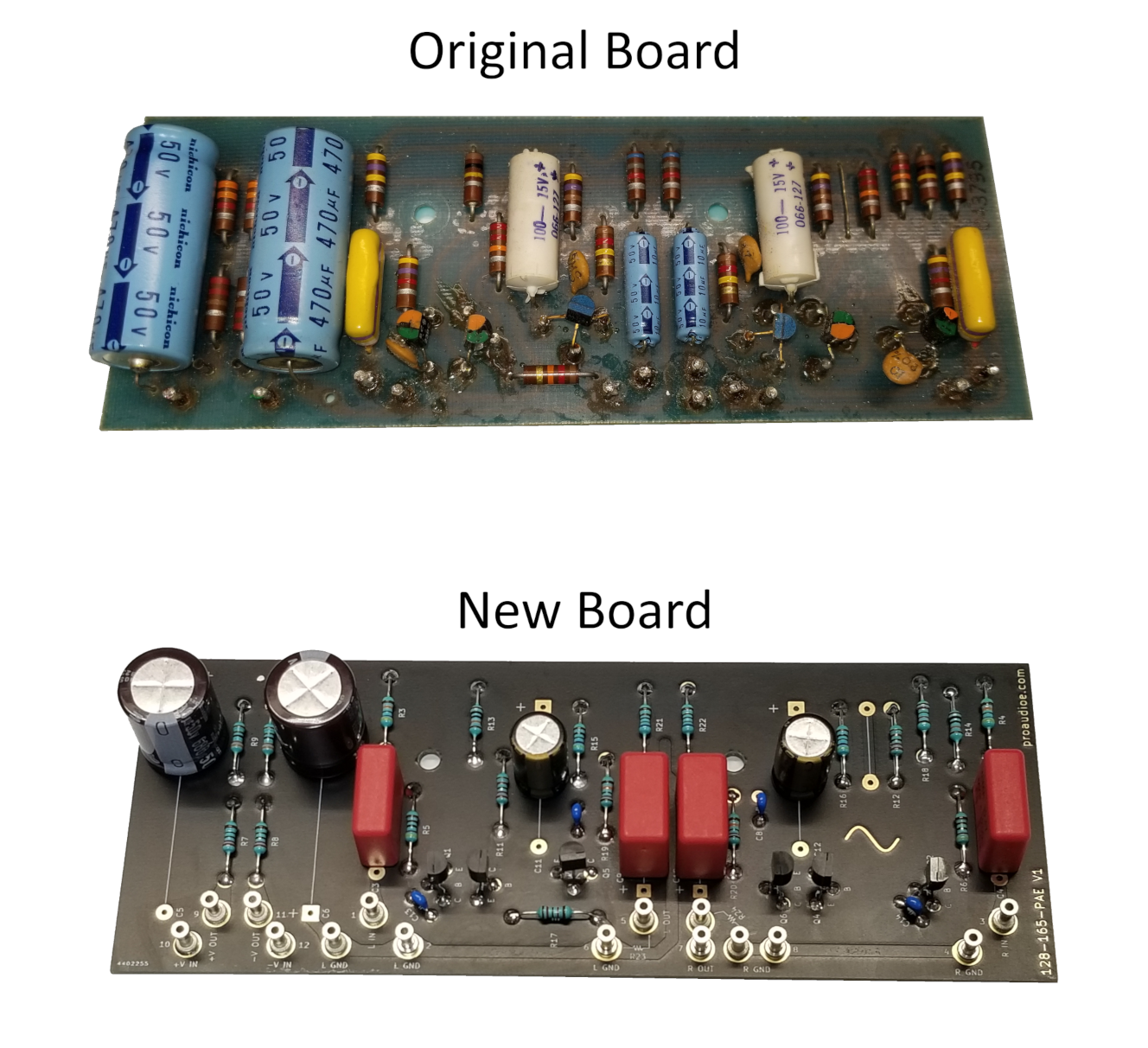
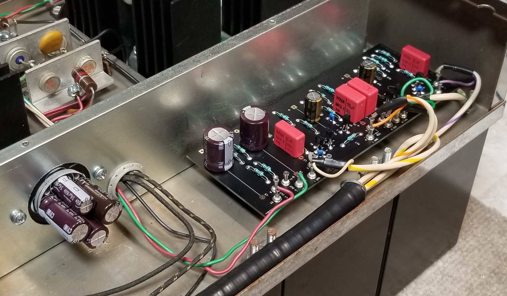
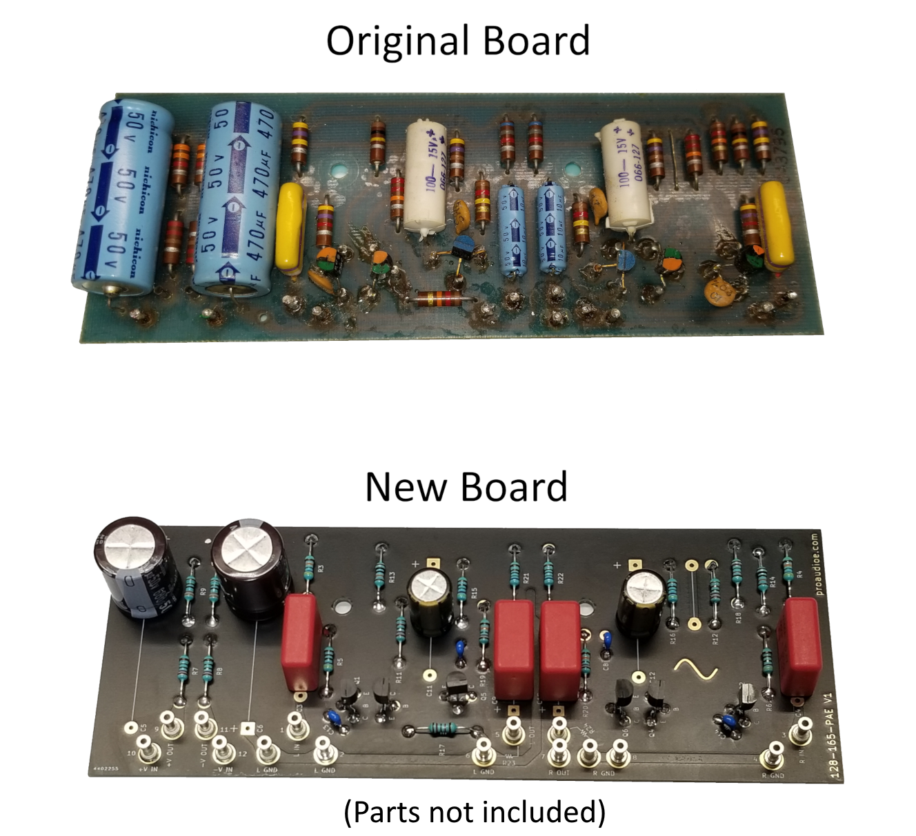
This is a new-production input preamp board for the McIntosh MC2100, MC2105, and MC2300 power amplifiers. This board follows the original component layout closely, and no changes were made to the original circuit design.

Includes the following:

  • One assembled and tested MC2100/2105/2300 input board
  • Anti-static bag for storing your original input board
  • 2 x Optional 22 kOhm resistors for MC2300’s below S/N 4Y426
  • Install guide with re-drawn schematic and board layout
  • Performance spec sheet

Here are the main differences between this board and the original:

  • Hand assembled with high quality components: TE Neohm LR1F series metal film resistors (1% tolerance, 600 mW, 50 ppm TCR), Nichicon electrolytic capacitors (UPM in supply filters, UKZ in audio stages), WIMA film capacitors, and new transistors. Robust wiring turrets replace the original hollow posts that wires are soldered to
  • Thick 2 oz. copper with gold finish (ENIG) and matte black soldermask
  • Silkscreen reference designators and symbols on both sides
  • All boards are burn-in tested for at least 24 hours and come with a performance spec sheet

We recommend testing your unit first to ensure it is working properly. If you are repairing your unit, please make sure your symptoms are originating from the preamp board before you replace it. Replacing this board will not resolve problems present in the rest of the unit, such as the power supply or amplifier sections. If you have not replaced the original multi-section can capacitor in your unit’s power supply, we recommend doing so; we offer a replacement capacitor kit with a custom designed PCB for this task.

Please do not attempt to install these boards if you are not thoroughly familiar with safely diagnosing, repairing, and testing amplifiers at the component level with test equipment (signal generator, oscilloscope, load, etc.) and a current-limited power supply.

Typical performance of both channels (Audio Precision analyzer, 2 Vrms output from DUT):

  • Gain: 20.83 dB
  • Frequency response: +0.01 dB, -0.04 dB from 20 Hz to 20 KHz
  • Signal to noise ratio: -97.1 dB below 2 V output (20 Hz – 22 KHz analyzer fltr, unwtd)
  • THD+N: Less than 0.007% from 20 Hz – 20 KHz (no analyzer fltr, unwtd)
  • IMD (DIN 250 Hz/8 KHz 4:1): Less than 0.005%

Note that these parameters apply to the preamp board by itself and do not reflect the overall performance of your McIntosh amplifier. We have tested an original MC2100 input board in the same manner and found that this new board slightly exceeds the performance of the original. Performance test sheet will include graphical sweeps of output amplitude vs. frequency, THD+N vs. frequency, phase shift vs. frequency, and crosstalk vs. frequency.

We also offer unassembled PCBs here.

MC2100, MC2105, MC2300 New Production Input Preamplifier PCB (Unassembled)

128-165-PAE-U

Click the link below to download the installation guide

This is a new-production input preamp PCB for the McIntosh MC2100, MC2105, and MC2300 power amplifiers. This board follows the original component layout closely, and no changes were made to the original circuit design.

Here are the main differences between this board and the original:

  • 2 oz. copper with a gold finish (ENIG), plated through-holes, and matte black soldermask
  • Silkscreen reference designators and symbols on both sides
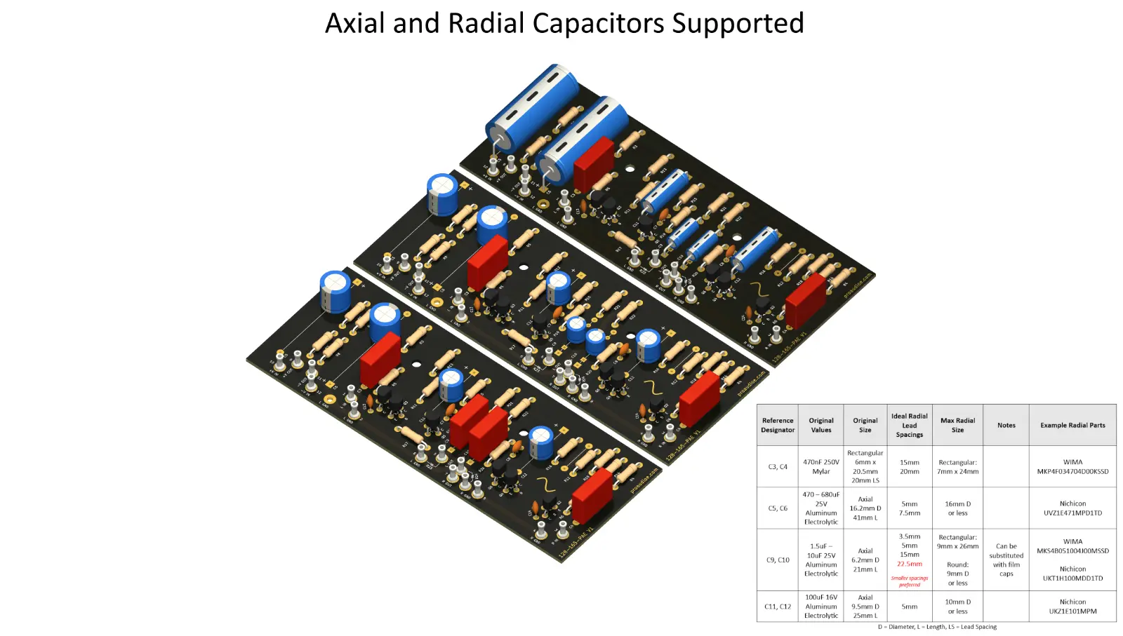
  • All component footprints are sized to fit the original parts. In addition, all axial electrolytic capacitors have footprints for radial parts of various sizes, both input film caps support two different lead spacings, and both electrolytic output caps can be substituted with film caps of the appropriate physical size. A capacitor sizing guide is included
  • Robust wiring turrets replace the original hollow posts that wires are soldered to

Includes one unpopulated input PCB, 15 wiring turrets, a resistor lead forming jig, an anti-static bag for storing your original board, and a thorough install guide with redrawn schematic, board layout, and parts list. You will need to order parts to assemble this board.

Please do not attempt to populate and install these boards if you are not thoroughly familiar with safely diagnosing, repairing, and testing amplifiers at the component level with test equipment (signal generator, oscilloscope, load, etc.) and a current-limited power supply.

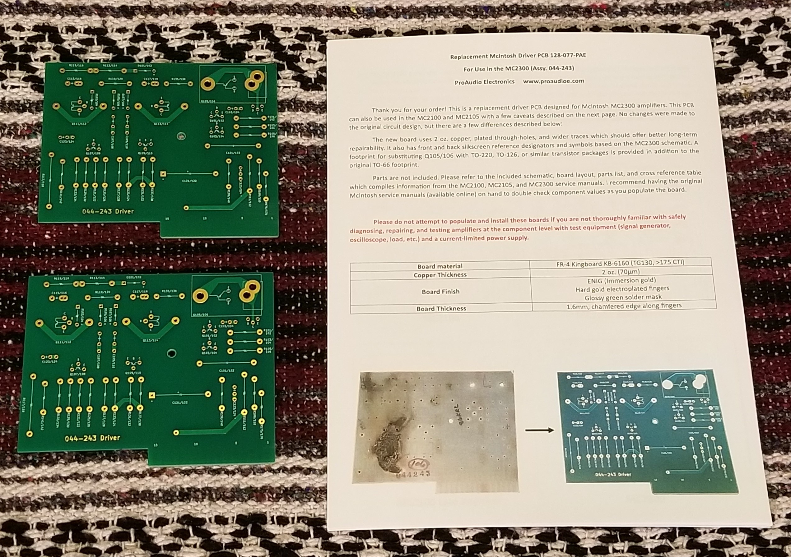
MC2100, MC2105, MC2300 New Production Driver Boards (Unpopulated)

128-077-PAE

Click the link below to download the installation guide

March 2024: These boards are currently out of stock, however we are working on a revision that will use all modern-production semiconductors and an improved circuit design.

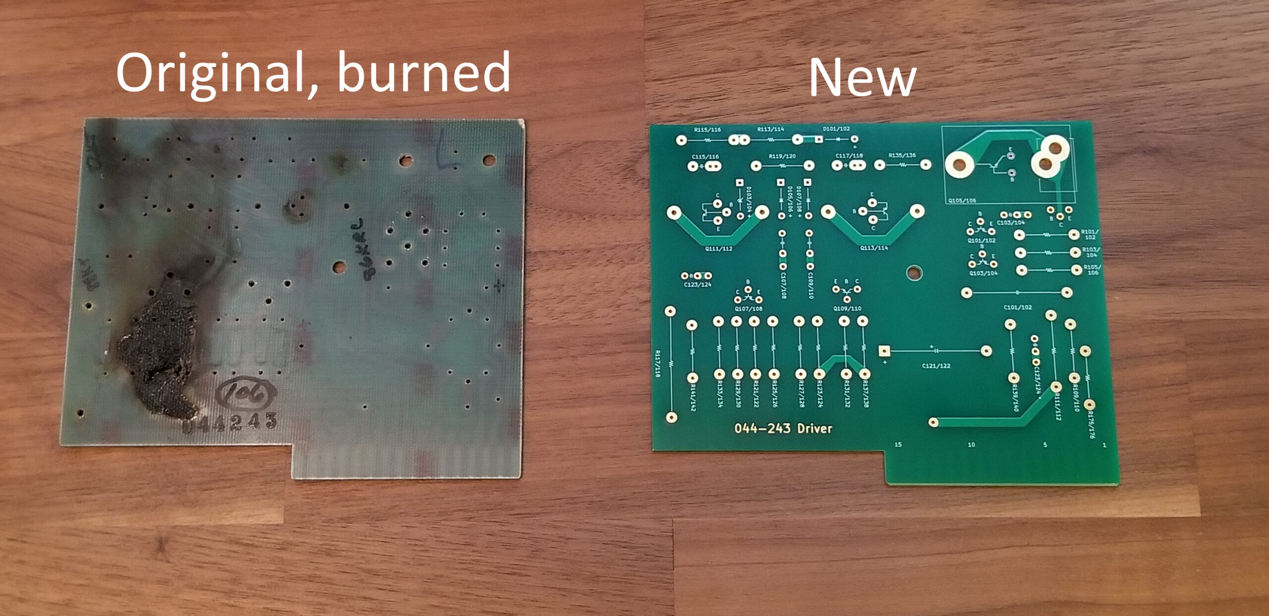
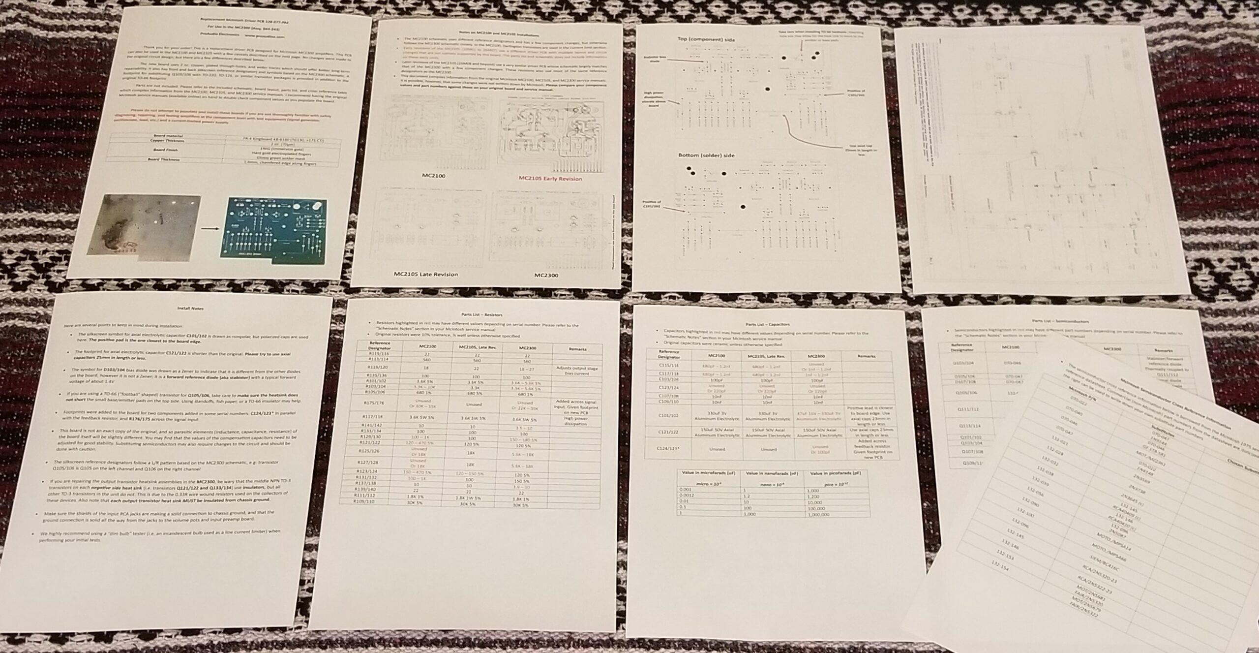
These PCBs are intended to replace damaged driver boards in the McIntosh MC2300 amplifier. The PCB itself was also used in other models such as the MC2100 and late-revision MC2105 units, and the new board should work in these models with some component changes. Bear in mind that the silkscreen reference designators/symbols are based on the MC2300 schematic, which largely matches the schematic of late-revision MC2105 units, but does not match the schematic of the MC2100. Early revision MC2105 units (s/n 10M01 to 26M07) used a slightly different PCB with multiple circuit and layout changes that would require modifications to the board to implement.

Includes two unpopulated PCBs, four TO-39 spacers, and a thorough install guide with re-drawn schematic, board layout, and parts list.

Please do not attempt to populate and install these boards if you are not thoroughly familiar with safely diagnosing, repairing, and testing amplifiers at the component level with test equipment (signal generator, oscilloscope, load, etc.) and a current-limited power supply.

Here are the main differences between this board and the original:

  • Plated through-holes, wider traces, 2 oz. copper with ENIG (gold) finish and hard-gold plated fingers (better long-term repairability)
  • Silkscreen with reference designators and symbols based on the MC2300 schematic
  • Footprint for the TO-66 (“football” shaped) transistor Q105/106 has pads for substituting it with a TO-220, TO-126, or similar package transistor
  • All original wire jumpers (driver collectors and feedback line) are implemented on the board as traces
  • A footprint is provided for the compensation cap that was put in parallel across the feedback resistor in some revisions (labeled C123/124*), as well as the resistor across the driver input (R175/176)
  • Two different lead spacings are provided for the ceramic disc cap footprints
  • Diode footprints use square pads for the negative terminals and polarized electrolytic capacitors use square pads for the positive terminals
  • Chamfered board edge around the fingers
  • Footprint for axial electrolytic capacitor C121/122 is a bit shorter than the original; please use axial caps around 25mm in length or less. C101/102 is the same length as the original; use axial caps 23mm in length or less.

Specifications:

  • Board material: FR-4 Kingboard KB-6160 (TG130, >175 CTI)
  • Copper thickness: 2 oz.
  • Board finish: ENIG (immersion gold), hard-hold plated fingers, glossy green solder mask
  • Width: 127.45 mm
  • Length: 105.10 mm
  • Thickness: 1.6 mm

Other Notes:

  • The PCB follows the general layout of the original, and no changes were made to the schematic, but it is not an exact replica. The parasitic elements of the board itself (inductance, capacitance, resistance) will thus be slightly different from the original board, and you may find that the values of the compensation capacitors need to be slightly adjusted for good stability. Substituting semiconductors may also require changes to the circuit and should be done with caution.
  • C101/102 on the silkscreen was drawn as a nonpolar cap, but polarized caps are typically used here. The positive terminal is the pad closest to the edge of the board.
  • The symbol for D103/104 bias diode was drawn as a Zener to indicate that it is not an “ordinary” diode, however it is not a Zener; it is a stabistor/forward reference diode with a typical forward voltage of around 1.4V (see service manual/semiconductor datasheet).
  • If using a TO-66 device for Q105/106, take care when installing the heatsink because the base/emitter leads have small pads on the top of the board that could touch the heatsink (i.e. collector) due to the size of the mounting holes. Using short standoffs, fish paper, or a TO-66 insulator underneath can help here.
  • The silkscreen reference designators follow a L/R pattern, so transistor Q105/106 is Q105 on the left channel and Q106 on the right channel.