MC2100-BR1
More information will be available soon.
More information will be available soon.
This board is a reproduction of McIntosh PCB 128279 which implements the power supply, protector, and headphone attenuator circuits in the MAC4100 receiver (assembly number 045217). The board layout follows that of the original, and no changes were made to the circuit design. The new PCB is manufactured with plated through-holes and 2-ounce copper to make the board more robust in the event that future repairs are needed. Silkscreen reference designators were also added to aid assembly.
This board is a reproduction of McIntosh PCB 128412 which implements the preamplifier, power amplifier driver, and power guard circuits in the MC2150 power amplifier (assembly number 045863). Slight layout changes were made to accommodate substitution of TO-202 voltage amplifier and current source transistors Q407 and Q414 with newer TO-126 devices, but the board layout otherwise closely follows that of the original. No changes were made to the circuit design. The new PCB is manufactured with plated through-holes to make the board more robust in the event that future repairs are needed, and silkscreen reference designators were also added to aid assembly.
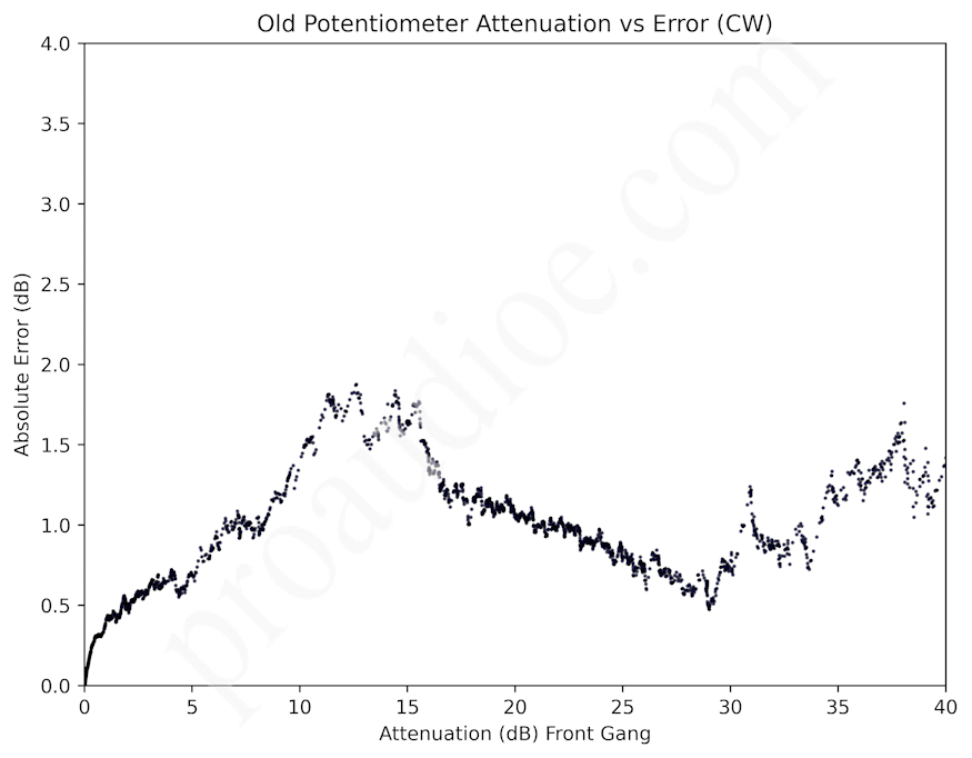
The original 2-gang volume potentiometers in McIntosh C26 preamplifiers frequently suffered from poor gang error across the pot’s rotation, causing the stereo image to audibly change position as volume is changed.
We created a solution that uses a high resolution digitally-controlled analog attenuator to implement a new volume pot with extremely good tracking between channels. The original pot can either be replaced with a single gang linear pot with integral AC switch, or one gang of the original audio taper pot can be used as the control signal. Care was taken to ensure that the output attenuation versus pot rotation law matches that of the original C26 pot.

This kit is designed to replace the original nickel plated steel RCA jacks used in the McIntosh C26 preamplifier with a set of gold plated Switchcraft connectors. The original connectors tend to get loose with age, and in models that utilized an aluminum mounting plate, the interface between the connectors and the plate was susceptible to galvanic corrosion over time. This kit eliminates these issues while maintaining the original star ground scheme.
The kit includes a replacement RCA mounting plate, 21 RCA connectors, all necessary mounting hardware, and a printed installation guide with pictures.
Please note that installing this kit is an extensive process that will involve drilling out the original isolated rivets, removing the cables attached to all RCA jacks, mounting the new jack plate in place, and re-soldering all cables. If you do not have prior experience doing work of this caliber on similar electronics, please have a qualified service professional install this kit in your unit.

This kit is designed to replace both 9000 uF/55 V electrolytic capacitors used in the Marantz 2245 and 2270 receivers. Other models may also be compatible. A custom designed PCB attaches to the mounting holes used by the original capacitors, providing footprints for two snap-in capacitors and eleven robust wiring turrets. This simplifies future capacitor replacement and allows for more flexibility when selecting new caps.
Included in the kit is a fully-assembled capacitor board with two Nichicon LGY series 10,000 uF/63 V capacitors pre-installed, all necessary mounting hardware, and an installation guide.
Installation
An install guide is included with the unit, but is also briefly listed below:
Parts Included

This is a set of two replacement program ROMs for the Oberheim OB-Xa synthesizer, preprogrammed with the latest OB-Xa software revision (XA-GA0 and XA-G1) released in February 1982.
The new ROMs are based around modern CMOS EEPROM devices manufactured by Atmel Corporation (now a part of Microchip), adapted to a 24-pin DIP footprint with a custom PCB and gold plated pins. These devices are fully compatible with the original NMOS UV EPROMS (ST M2732A-2), have TTL and CMOS compatible inputs and outputs, and offer a significant reduction in current draw: up to a 68% decrease under normal operating conditions, and up to a 94% decrease in standby mode.
All ROM boards are hand assembled in the USA and tested in an Oberheim OB-Xa to guarantee their functionality.
If you are ordering these to repair an OB-Xa with a nonfunctional computer, please note that in our experience it is not uncommon for these units to have one or more dead logic ICs on the upper or lower control boards. Thus, it is possible that your original ROMs are fine, but another component in the system has failed.
ROM CRC-32 Checksums:
XA-GA0: F8268EA0
XA-G1: B32DCB5D
Click here to download the installation guide

This kit is designed to replace both multi-section can capacitors used in the power supply section of the McIntosh C26 preamplifier. Two custom capacitor mounting boards and four 220uF/200V Nichicon electrolytic capacitors are included. These provide a slight improvement in supply filtration compared to the original parts which, depending on serial number, typically included one 160uF/200V and one 200uF/150V capacitor per can. If you need different capacitor values, feel free to send us a message and we can order them for you.
Parts Included

This kit can be used to isolate our 4-in-1 can capacitor replacement PCBs from chassis ground. This is useful in cases where the original installation used an insulated can floating from chassis.
Includes one insulator PCB for 1-3/8 inch diameter cans with 46 mm CTC mounting holes, two nylon #6-32 screws, and two nylon #6-32 hex nuts.

This kit is intended as an easy way to replace old multi-section can capacitors around 1-3/8″ diameter (approx. 35 mm) with 46 mm CTC mounting hole spacing. These cans were often used in vintage audio and radio equipment, such as McIntosh, Marantz, Heathkit, and Dynaco.
The capacitor board fits up to four 7.5 mm lead spacing, 16 mm diameter radial capacitors. Smaller 5 mm lead spacing capacitors will also fit. An alternate version of this kit designed specifically for 5 mm lead spacing, 12.5 mm diameter capacitors is also available.
The negative leads of all capacitors are connected to a thick outer copper ring and two plated mounting holes. This means the negatives will be tied to chassis ground by default. If you need to isolate this board from chassis, take a look at our isolation kit.
Includes one capacitor mounting board, one spacer board, 5 wiring turrets (one extra), a mounting hardware kit, and a link to installation instructions. Capacitors are not included. In order to save on paper and toner, we are now including a link to a PDF copy of the installation guide. If you would prefer a hard copy, please let us know and we’d be happy to accommodate.
Based on the IPC-2221B standard, this kit is not to be installed in circuits that will see peak voltages greater than 600 V.
Specifications:
Note: Dimensions are nominal values. Outline dimensions may vary by ±0.15 mm, and hole sizes by ±0.076 mm
Click here to order: With Capacitors, Without Capacitors
Click here to download the installation guide: With Capacitors, Without Capacitors

This kit replaces both dual electrolytic capacitors used in the Marantz 2385 and 2500 with four modern-production, Kemet 8200uF/100V 105°C screw-in capacitors. Available with or without capacitors.
A custom capacitor mounting board attaches to the Marantz via four pre-existing screw holes. Wiring is done from the bottom of the unit and is made easier by the use of robust wiring turrets. Footprints are provided for installing the bleeder resistors on the circuit board, but they can also be left where they are and attached to the wiring turrets. The mounting board itself is manufactured with double-sided 2 ounce copper and large copper pours to ensure very low impedance connections to the turrets, a 2.4 mm thick FR-4 laminate to reduce board flex, and a gold finish.
If you are ordering this kit without capacitors, please see the section What You Will Need below:
What You Will Need
The mounting board was designed to fit four Kemet ALS80A822DF100, which is an 8200 uF/100 V screw-in capacitor. These do not ship with the necessary screws, so you will also need eight M5-0.8 x 12 mm machine screws with head diameter 11 mm or less (e.g. Prime-Line 9131367) and eight M5 internal tooth lock washers.
The dimensions of the Kemet capacitors are 36 mm diameter, 107 mm height, 12.80 mm CTC mounting stud spacing, and it uses M5-0.8 threads. I recommend using this specific part (or one in the same family, ALS80-A-DF). If you need to select a different capacitor, there are some important caveats listed below:
If you have any doubts about the fitment of your choice of replacement capacitors, feel free to send us a message.
Parts Included (With Caps)
Parts Included (Without Caps)

This kit is intended as an easy way to mount new radial electrolytic capacitors when replacing 1 inch diameter multi section can capacitors with 1.5 inch mounting hole spacing CTC. This design was modeled after an Astron A-25-65 can. These were often used in vintage radio equipment.
Up to three different caps can be installed, and they all share a common lead located in the center. The center common lead has a trace connecting it to one of the mounting holes, making it convenient to tie to chassis ground; if you need to isolate this board from chassis ground, take a look at our insulation kit. The spacer board sits between the new caps and mounting board and adds clearance between the turrets and cans of the caps. Four turrets provide a robust post for wires and other components to attach to when installing.
If you use a positive-common configuration, be wary that the cans of electrolytic caps are often tied to the negative lead (cathode), but not always. Thus, voltages may exist between the cans depending on the circuit, so space them apart as needed.
Based on IPC-2221B guidelines, this board is not to be used in circuits that may see peak voltages above 450 V assuming a typical negative-common configuration.
Specifications:
Note: Dimensions are nominal values. Outline dimensions may vary by ±0.15mm, and hole sizes by ±0.076mm.

This kit is intended as an easy way to replace old multi-section can capacitors around 1-3/8″ diameter (approx. 35 mm) with 46 mm CTC mounting hole spacing. These cans were often used in vintage audio and radio equipment, such as McIntosh, Marantz, Heathkit, and Dynaco.
The capacitor board fits up to four 5 mm lead spacing, 12.5 mm diameter radial capacitors. An alternate version of this kit designed for larger 7.5 mm lead spacing, 16 mm diameter capacitors is also available.
The negative leads of all capacitors are connected to a thick outer copper ring and two plated mounting holes. This means the negatives will be tied to chassis ground by default. If you need to isolate this board from chassis, take a look at our isolation kit.
Includes one capacitor mounting board, one spacer board, 5 wiring turrets, a mounting hardware kit, and a link to installation instructions. Capacitors are not included. In order to save on paper and toner, we are now including a link to a PDF copy of the installation guide. If you would prefer a hard copy, please let us know and we’d be happy to accommodate.
Based on the IPC-2221B standard, this kit is not to be installed in circuits that will see peak voltages greater than 600 V.
Specifications:
Note: Dimensions are nominal values. Outline dimensions may vary by ±0.15 mm, and hole sizes by ±0.076 mm

This is a 10 cm diameter wheel made of FR-4 (typical PCB material) that combines Ohm’s Law and Joule’s Law into one handy reference chart. To calculate one of the inner quantities, use two known quantities and the appropriate outer expression. Example: the power dissipated by a 1 kOhm resistor with 100 mA flowing through it is P = I2R = 0.12 A * 1000 Ohm = 10 W. This particular relationship is called Joule heating or Joule’s first law.
The reverse side features the likenesses of Georg Simon Ohm and James Prescott Joule. Electrical engineers, technicians, and hobbyists alike utilize these laws on a daily basis.
Available in green/gold, black/gold, red/gold, and laser etched wood. Note: The wood version does not have the portrait of Ohm and Joule on the back.
“If I have seen further, it is by standing on the shoulders of giants.”
— Excerpt from a 1675 letter from Sir Isaac Newton to Robert Hooke
Specifications:
If you know a friend or family member who would appreciate a PCB medallion with custom artwork on it as a gift (e.g. a picture of a pet, loved one, etc.), we’d love to help you get some manufactured. They also make great Christmas ornaments. Please contact “parts (at) proaudioe.com” for more information. We can order as few as 5 PCBs.

This is an FPGA implementation of the MN4760S line memory used in the time base corrector (TBC) sections of some LaserDisc players. This board was designed specifically for an MLD7020 with a dead line memory, breathing some new life into a unit that would have otherwise been a paperweight due to the original part no longer being manufactured.
This board is not available for order at this time. Please contact “parts (at) proaudioe.com” if you would like additional information.
Click here to download the installation guide

This kit is designed to replace the original riveted RCA jacks used on the back of McIntosh MAC4100 receivers. A custom RCA mounting board re-uses the original rivet holes for attaching to the back panel and provides plated holes for soldering the input/output shielded cables. The mounting board uses 2 ounce copper and wide traces to connect each RCA jack to their respective solder pads, and the star ground arrangement of the original wiring scheme is maintained. A matte black cover plate is included for replacing the original black shrouds around the RCA jacks.
Please note that the installation process for this kit is fairly complex and will involve drilling out the original RCA rivets, soldering the new RCA jacks to the mounting board, stripping and soldering each shielded cable to the new board, and mounting the new board in place. We recommend testing your unit before installation to ensure everything is working as expected, and then taking plenty of pictures throughout the process to use as reference.
Note: The included black machine screws will be slightly shorter than those in the listing photos to avoid having extra thread length sticking off of the back.
Parts Included
Additional Details

This is a replacement power guard display PCB for McIntosh MC2500 amplifiers. This board is used to mount four bi-pin incandescent lamps which indicate the power guard status for both channels of the MC2500.
Includes one unpopulated PCB and one gold plated 5 pin right angle Molex connector. Lamps are not included.
The hole sizes for the lamps were increased to accommodate PC pin sockets (not included) for simplifying future lamp replacement. If you have LED replacements for 7382 lamps that are designed to be powered with AC, they should also work just as well on this board.
Specifications:

This is a replacement kit for the GE multi-section can capacitors used inside the McIntosh MC2100, MC2105, and MC2300 power amplifiers. These cans were stamped with McIntosh part number 066-095. Other models may also use this can. High quality, genuine Nichicon capacitors rated for operation up to 105°C are used to ensure a long operational lifespan, and a custom PCB with thick 2 oz. copper provides a robust and elegant mounting solution. Four wiring turrets facilitate the connections to each of the four caps. No more gutting the old cans and sticking new caps inside!
Includes four Nichicon capacitors, one cap mounting PCB, one spacer PCB, a hardware kit, and a thorough step-by-step installation guide.
Installing this kit will require soldering, drilling out the original can’s mounting rivets, and stripping/attaching wires in a tight space. If you do not have prior experience safely testing and repairing amplifiers at the component level, please have a qualified professional install this kit in your unit.
The following capacitor values are included:
Note: The capacitor symbols (square, triangle, half-circle, dash) on the cap PCB were arranged based on the orientation of the original can in the MC2300. Other models, such as the MC2100, typically had the cans oriented differently, meaning the position of the symbols on this board may not align with your original installation.

This is a new-production input preamp board for the McIntosh MC2100, MC2105, and MC2300 power amplifiers. This board follows the original component layout closely, and no changes were made to the original circuit design.
The new PCB is double-sided and is manufactured with plated through-holes and a gold finish. Silkscreen reference designators and symbols are provided on both sides. Robust wiring turrets replace the original hollow posts that cables solder to. All component footprints are sized to fit the original parts. In addition, all axial electrolytic capacitors have footprints for radial parts of various sizes, both input film caps support two different lead spacings, and both electrolytic output caps can be substituted with film caps of the appropriate physical size. A capacitor sizing guide is included with unpopulated kits.
Assembled boards are built using high quality components, including Vishay MRS25 series low noise metal film resistors (1% tolerance, 600 mW, 50 ppm TCR), Nichicon electrolytic capacitors (UPM series for supply filters, UKZ for audio stages), WIMA film capacitors, and new transistors. All assembled boards are burn-in tested for 24 hours and run through an Audio Precision analyzer to confirm that they meet the performance specifications listed below.
Parts Included (Assembled Board)
Parts Included (Unpopulated PCB)
Typical Performance
Typical performance of both channels (Audio Precision analyzer, 2 Vrms output from DUT):
Note that these specifications apply to the preamp board by itself and do not reflect the overall performance of your McIntosh amplifier. We have tested an original MC2100 input board in the same manner and found that this new board slightly exceeds the performance of the original.
We recommend testing your unit first to ensure it is working properly. If you are repairing your unit, please make sure your symptoms are originating from the preamp board before you replace it. Replacing this board will not resolve problems present in the rest of the unit, such as the power supply or amplifier sections. If you have not replaced the original multi-section can capacitor in your unit’s power supply, we recommend doing so; we offer a replacement capacitor kit with a custom designed PCB for this task.
Please do not attempt to install these boards if you are not thoroughly familiar with safely diagnosing, repairing, and testing amplifiers at the component level with test equipment (signal generator, oscilloscope, load, etc.) and a current-limited power supply.


