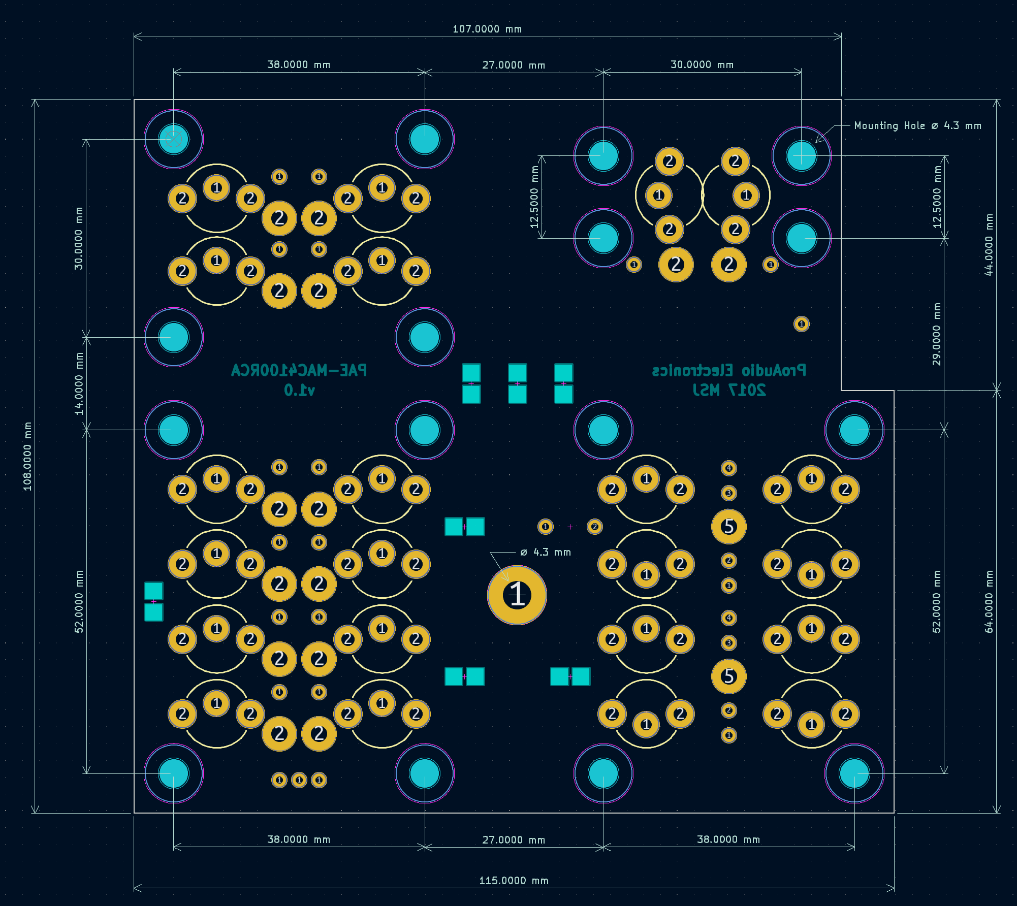
PAE-MAC4100RCA
Click the link below to download the installation guide
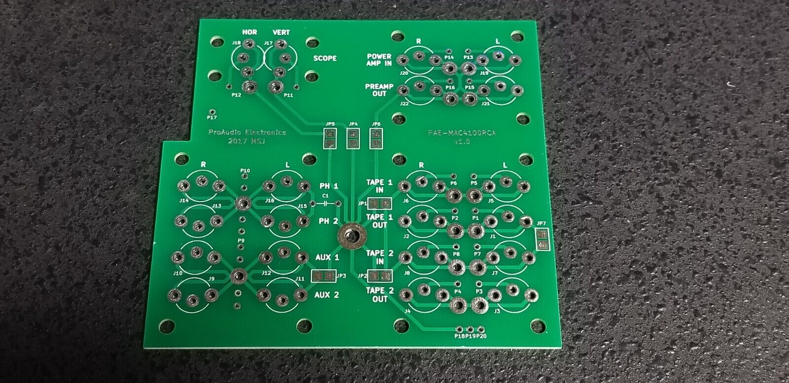
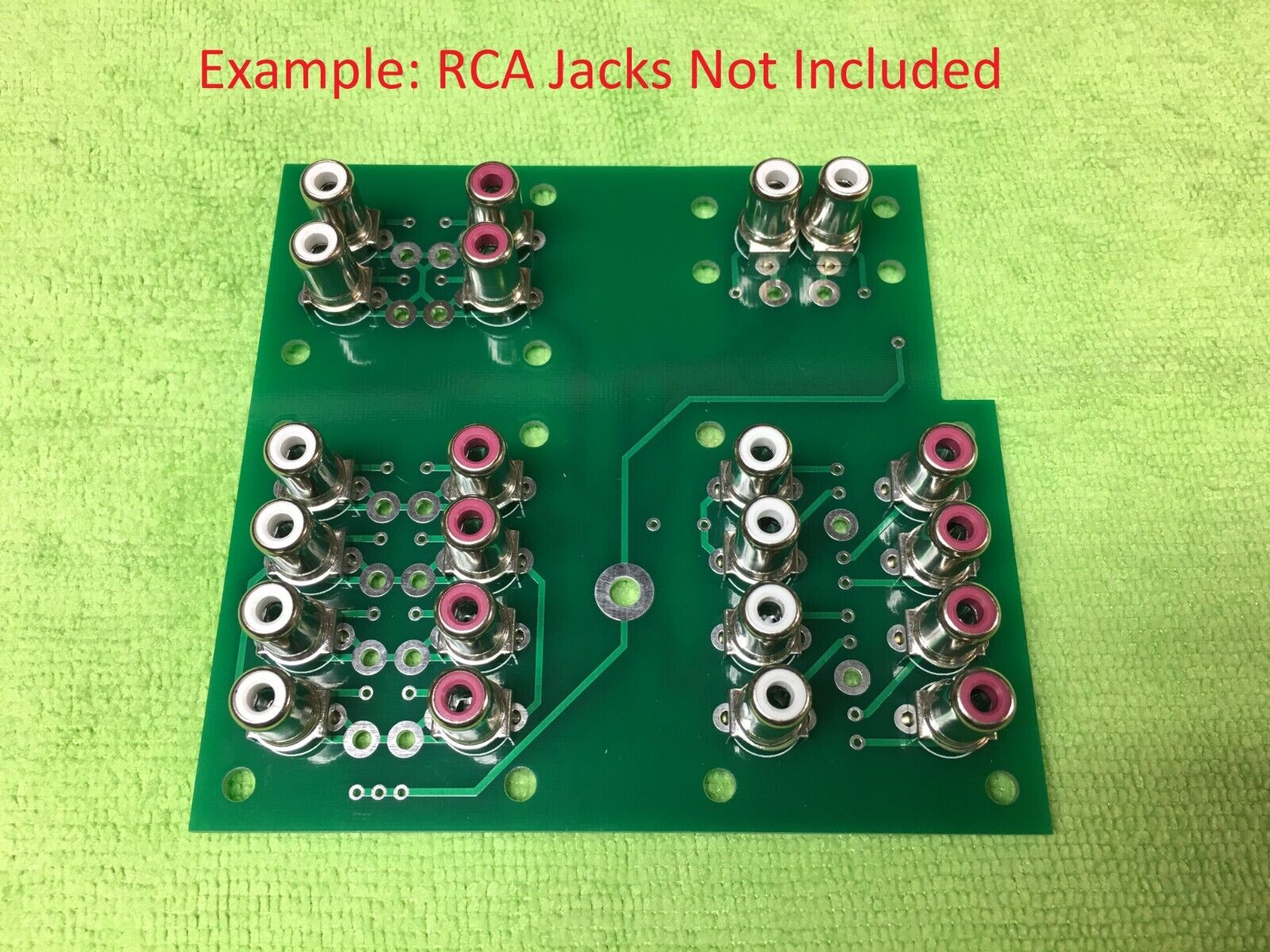
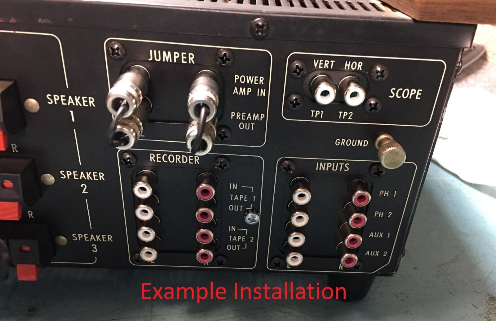
This board was created as a solution for replacing the original riveted RCA jacks on the McIntosh MAC4100. The new RCA jacks (CUI RCJ-022 and RCJ-023) are not the most premium connectors in the world, but if your original jacks are loose and intermittent, these will certainly perform better.
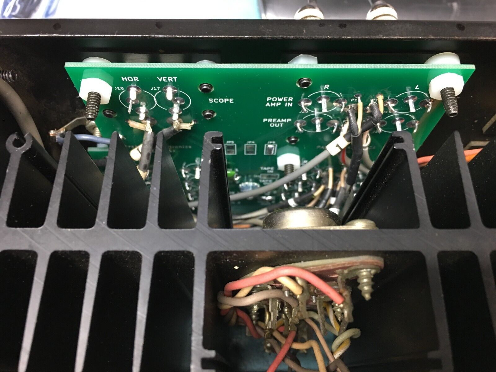
The rivets holding the original RCA jacks in will need to be removed and replaced with #6-32 screws. The board will also need standoffs or spacers to keep it far enough away from the back panel. The original black plastic shrouds can be placed over the new RCA jacks so that the green PCB is not seen from the back panel.
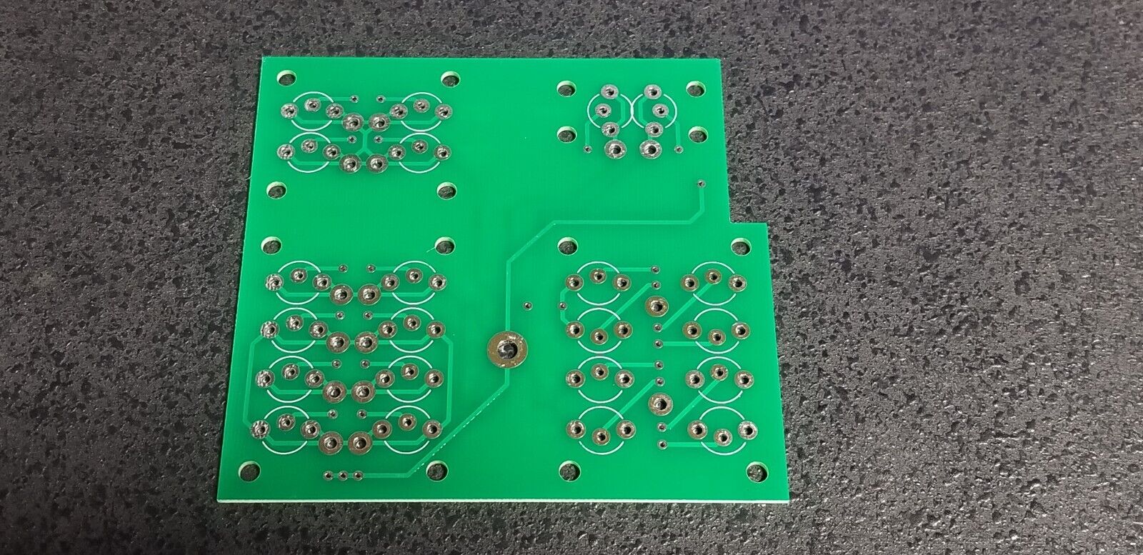
Includes one unpopulated PCB and a schematic of the board. RCA jacks are not included.
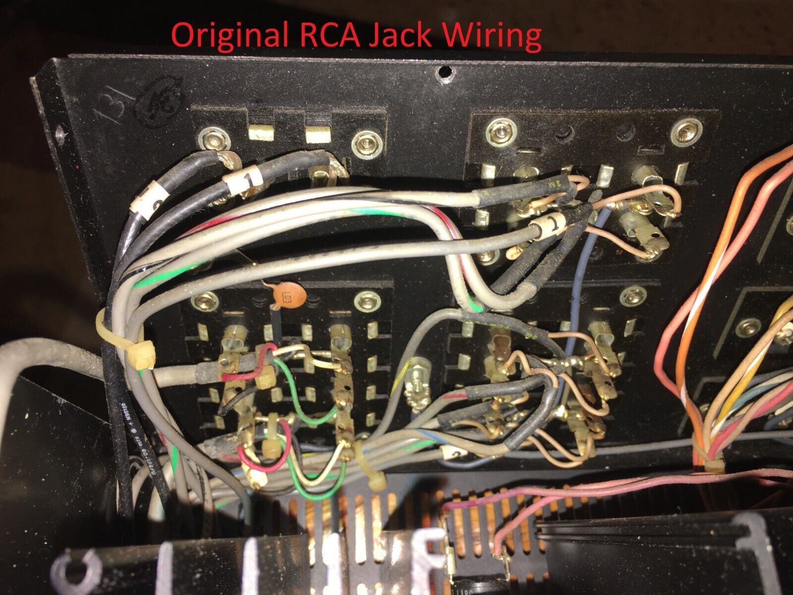
This board is quite involved to install and will require the back panel of your unit to be taken off. Please do not attempt to assemble and install it if you are not familiar with safely diagnosing and repairing electronics. Be sure to take lots of pictures of your original installation so you know where everything goes.
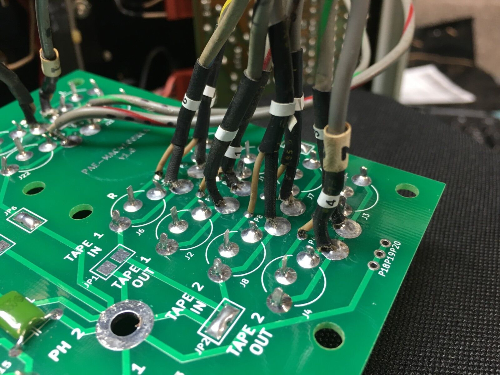
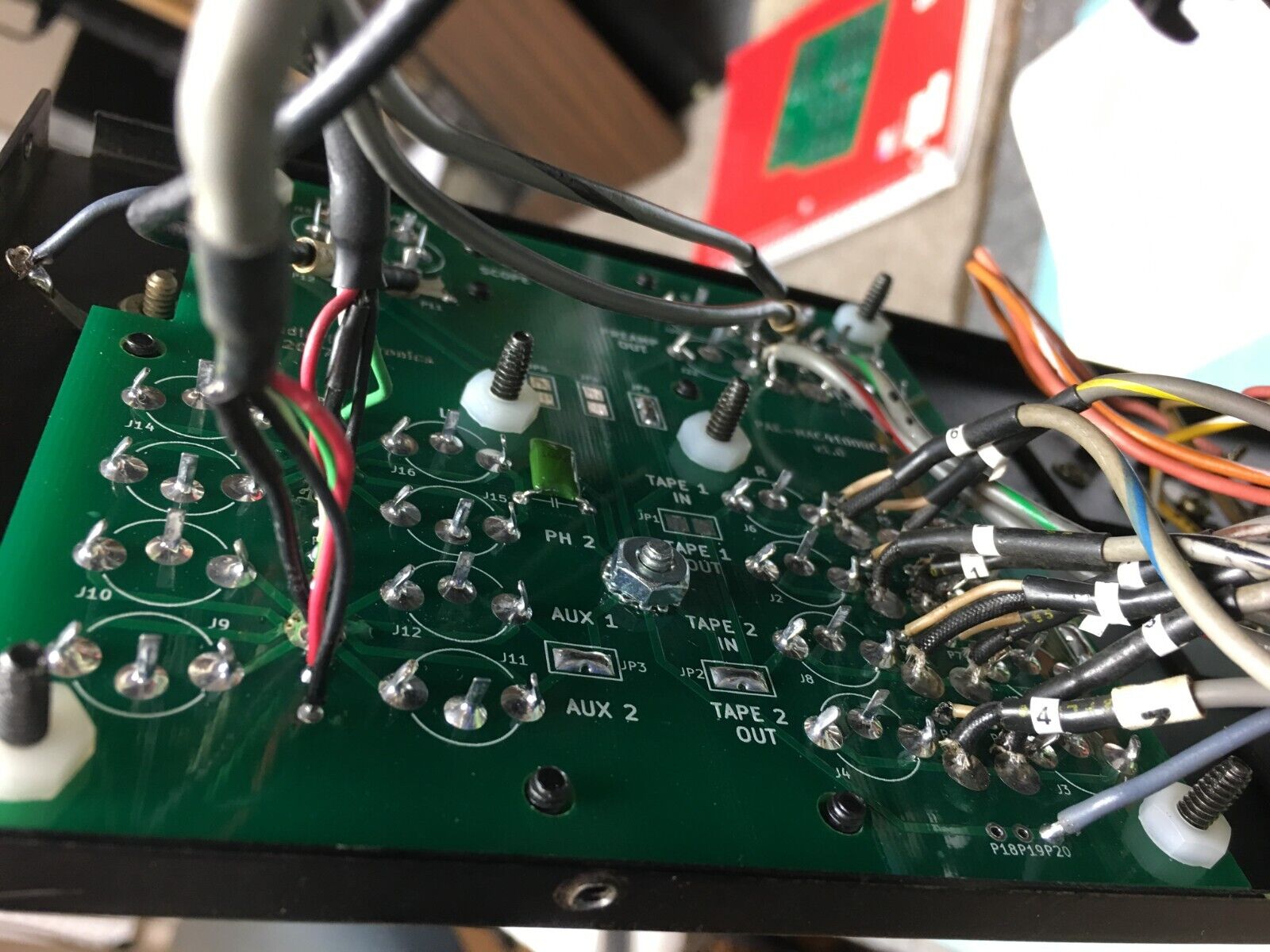
Depending on the serial number of your unit, the wiring scheme may be slightly different. This board has the following optional solder jumpers:
- JP1 or JP2: Short to connect the shields of the “TAPE 1 and 2 IN” jacks to chassis ground (JP1 and JP2 are redundant, use either one)
- JP3: Short to connect the shields of the “AUX 1 and 2” jacks to chassis ground
- JP4: Short to connect the shields of the “SCOPE VERT” jack to chassis ground
- JP5: Short to connect the shields of the “SCOPE HOR” jack to chassis ground
- JP6: Short to connect the shields of the “PREAMP OUT” and “POWER AMP IN” jacks to chassis ground
- JP7: Short to connect the shields of the “TAPE 1 and 2 OUT” jacks to the shields of the “TAPE 1 and 2 IN” jacks
For example, in the unit we installed this board in, the shields of the AUX, TAPE OUT, TAPE IN, and PRE OUT/POWER IN jacks were tied to the chassis grounding screw by the factory. This corresponds to shorting JP3, JP1 or JP2, JP7, and JP6. Additionally, there was a 10nF capacitor between the shields of the PHONO jacks and chassis ground, which is implemented as the capacitor footprint C1.
Mounting Hardware (not included):
Unfortunately we did not record the exact hardware used when installing this board in 2017. Based on the pictures, however, we believe that 1/2″ long #6-32 machine screws will be ideal. Each screw needs to clear the thickness of the metal back panel (~1.6 mm), the black cover pieces (~1.6 mm), a set of nylon hex nuts or spacers (~4 mm), the green RCA jack board (1.6 mm), and a final set of hex nuts (~3 mm). That adds up to 11.8 mm, or about 0.46 inches, so 1/2″ screws should work well. Essentra P/N 0400632HN should work well for the nylon hex nuts, but you’ll need to add some flat washers (e.g. Keystone P/N 3122) as well to get the RCA jack clearance right. Alternatively, one buyer let us know that 4 mm hollow plastic spacers worked well for them (e.g. HPS-8-4.2-4-N from Accu-Components).
Note that the spacing between the black cover pieces and the surface of the green RCA jack board should be about 4 mm or greater in order to prevent the “shoulders” of the RCA jacks from interfering. We recommend using nylon hardware for this because the jack board has a couple of traces run near some of the mounting holes. For the star ground point, use stainless steel hardware with an internal tooth lock washer underneath the screw head and the hex nut.
If you have any questions, please feel free to send us a message.
If you are interested, please contact us.

