128-165-PAE-A
Click the link below to download the installation guide:
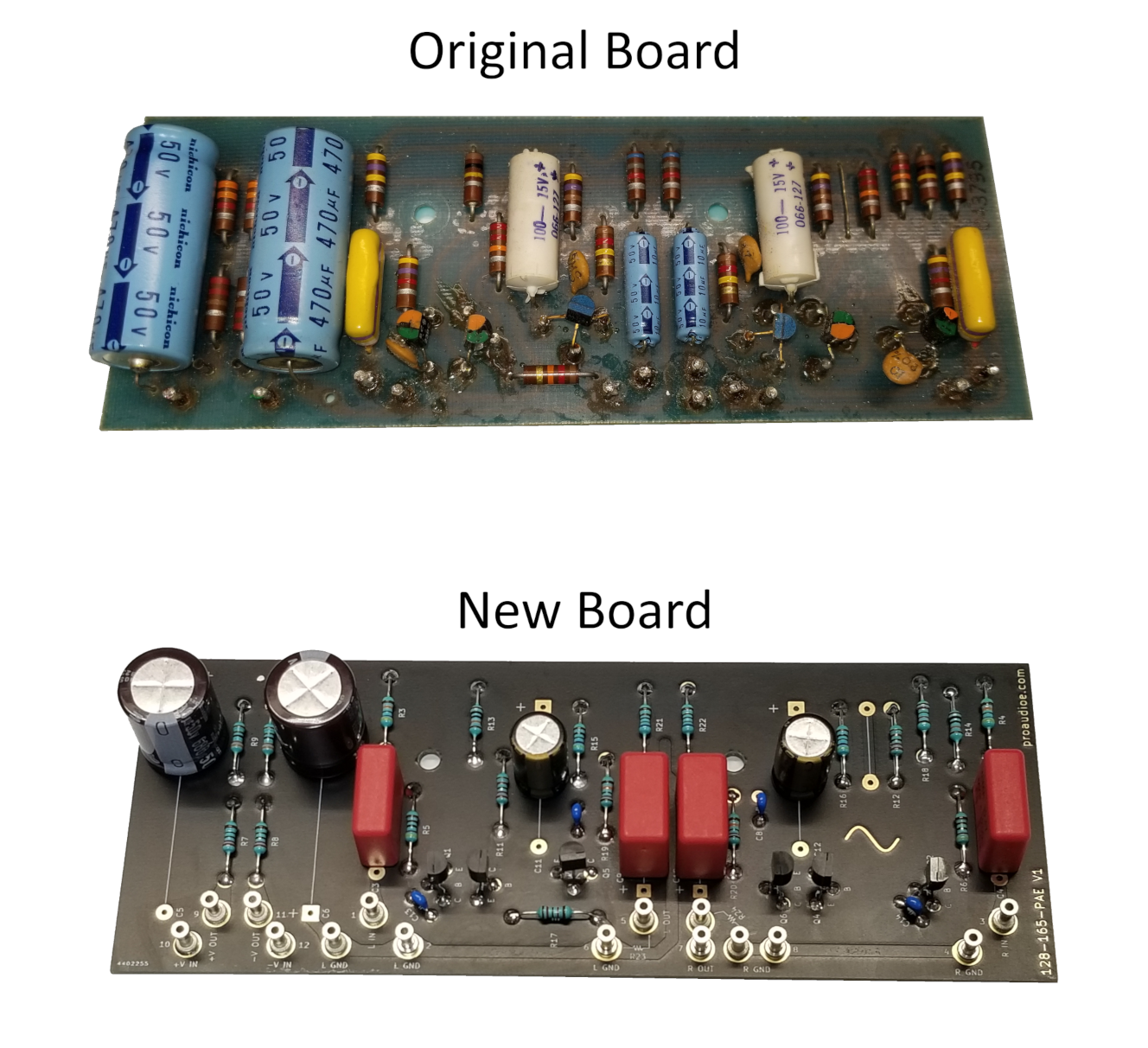
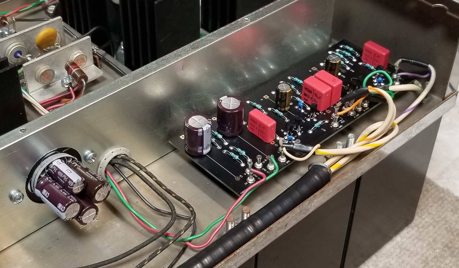
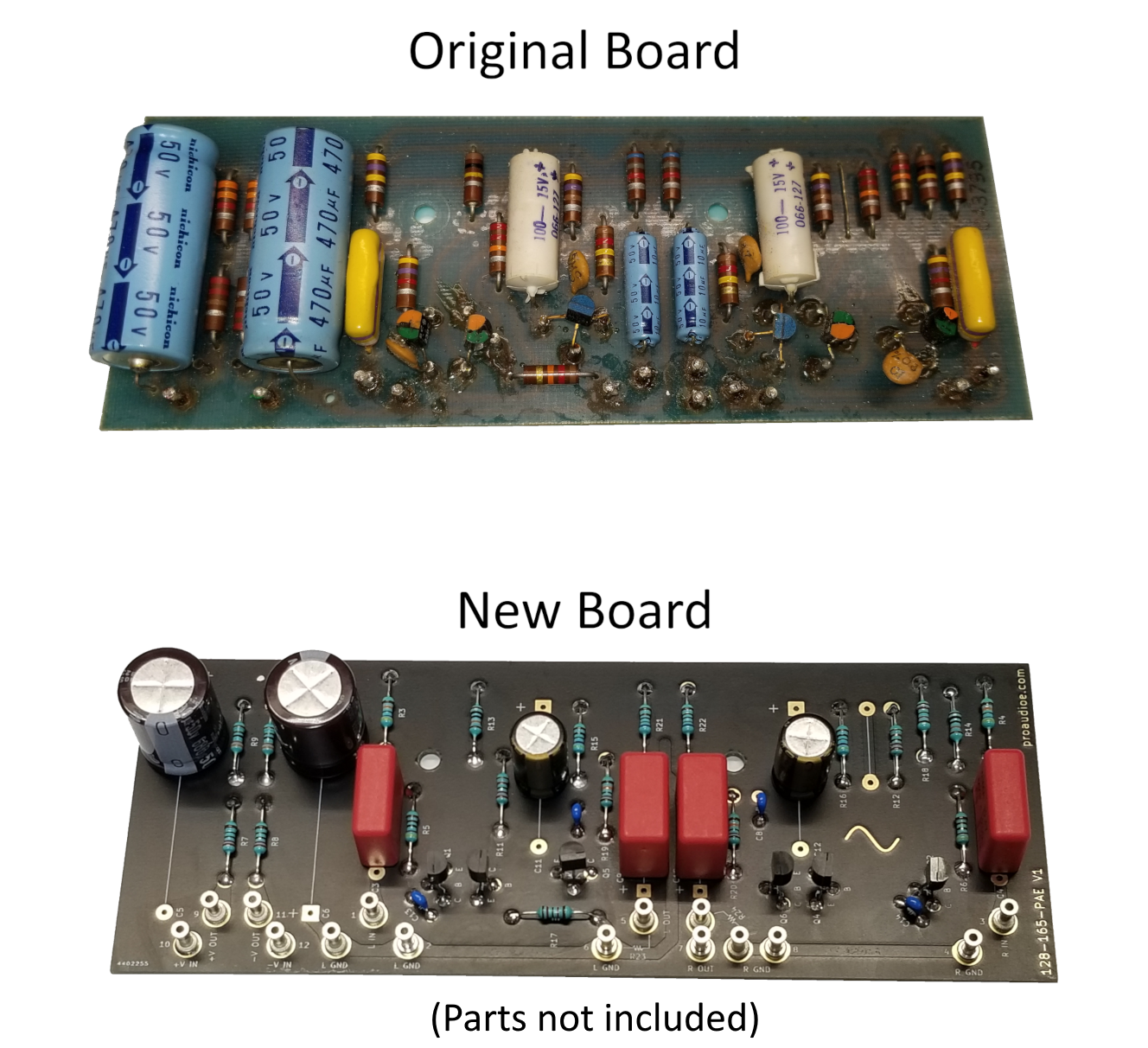
This is a new-production input preamp board for the McIntosh MC2100, MC2105, and MC2300 power amplifiers. This board follows the original component layout closely, and no changes were made to the original circuit design.
Includes the following:
- One assembled and tested MC2100/2105/2300 input board
- Anti-static bag for storing your original input board
- 2 x Optional 22 kOhm resistors for MC2300’s below S/N 4Y426
- Install guide with re-drawn schematic and board layout
- Performance spec sheet
Here are the main differences between this board and the original:
- Hand assembled with high quality components: TE Neohm LR1F series metal film resistors (1% tolerance, 600 mW, 50 ppm TCR), Nichicon electrolytic capacitors (UPM in supply filters, UKZ in audio stages), WIMA film capacitors, and new transistors. Robust wiring turrets replace the original hollow posts that wires are soldered to
- Thick 2 oz. copper with gold finish (ENIG) and matte black soldermask
- Silkscreen reference designators and symbols on both sides
- All boards are burn-in tested for at least 24 hours and come with a performance spec sheet
We recommend testing your unit first to ensure it is working properly. If you are repairing your unit, please make sure your symptoms are originating from the preamp board before you replace it. Replacing this board will not resolve problems present in the rest of the unit, such as the power supply or amplifier sections. If you have not replaced the original multi-section can capacitor in your unit’s power supply, we recommend doing so; we offer a replacement capacitor kit with a custom designed PCB for this task.
Please do not attempt to install these boards if you are not thoroughly familiar with safely diagnosing, repairing, and testing amplifiers at the component level with test equipment (signal generator, oscilloscope, load, etc.) and a current-limited power supply.
Typical performance of both channels (Audio Precision analyzer, 2 Vrms output from DUT):
- Gain: 20.83 dB
- Frequency response: +0.01 dB, -0.04 dB from 20 Hz to 20 KHz
- Signal to noise ratio: -97.1 dB below 2 V output (20 Hz – 22 KHz analyzer fltr, unwtd)
- THD+N: Less than 0.007% from 20 Hz – 20 KHz (no analyzer fltr, unwtd)
- IMD (DIN 250 Hz/8 KHz 4:1): Less than 0.005%
Note that these parameters apply to the preamp board by itself and do not reflect the overall performance of your McIntosh amplifier. We have tested an original MC2100 input board in the same manner and found that this new board slightly exceeds the performance of the original. Performance test sheet will include graphical sweeps of output amplitude vs. frequency, THD+N vs. frequency, phase shift vs. frequency, and crosstalk vs. frequency.
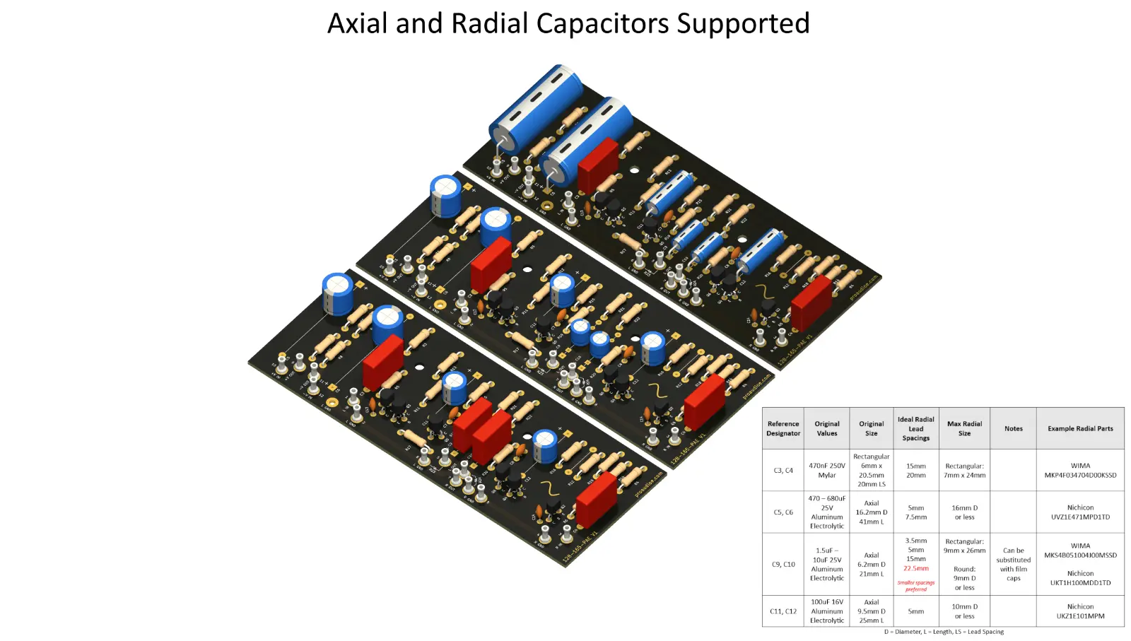
We also offer unassembled PCBs here.


